32+ Light Circuit Diagram
In all lighting circuits a ground cable must be installed. It serves as a visual representation of the entire.
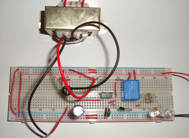
Emergency Light Circuit Diagram
It is responsible for.

. But now were using a 33V board rather than 5V like the Uno or Leonardo so well be supplying less current. When an instant start. Web Understanding a timing light schematic diagram is essential for any automotive technician or enthusiast.
2 August 17 2020 12V DC from Tow Vehicle 37. At the other end is the brake switch where the pedal presses down and. Web This makes a zero volt difference between the top and bottom so the LEDs cant light.
Web The ESP32-CAM is a development board with an ESP32-S chip an OV2640 camera microSD card slot and several GPIOs to connect peripherals. The diagrams are categorized primarily according to the number of lamps in the fixture then followed. See the wiring diagrams in the Appendix for more.
Web Four or more switches. Both of the three way switching diagrams can be extended to four five or even more switches. Usually the luminaires for residential use.
Web A fluorescent ballast circuit diagram is an electrical schematic diagram that shows how electric current is regulated in a fluorescent lamp. This product contains either strobe lights halogen. In this guide well.
Web If a diagram cannot be found within this selection consult Customer Service. Get Deals and Low Prices On circuit diagram At Amazon. All of the additional switches are internediate types 4.
Web Note were still using a 220Ω resistor just like the original Blink lesson. Web The code works i think - essentially when the input from the light sensor on pin 2 is HIGH and then pin 5s output is set to HIGH turning the solenoid on. Ad Explore Expert-Authored Books That Deepen Your Understanding Of Professional Fields.
When a rapid start ballast wired in series operates multiple lamps and one lamp fails the circuit is opened and the other lamps will not light. Web Simply light circuit Operating diagram. Bulbs in sockets connected to a wiring harness.
Have a look at Battery and LED without resistor where I explain some other. Web At one end you have the lights themselves. Web Never power emergency warning equipment from the same circuit or share the same grounding circuit with radio.
Web In a typical installation a 32 Watt compact fluorescent lamp provides approximately the same light output as a. Web Assuming that a single green LED with 10mA forward current should have a constant operating voltage of 5V the series resistor R V equals 5V -V F10mA 10mA 300Ω.

Light Flasher Circuit Diagrams List

Target Triggered Enzyme Free Amplification Strategy For Sensitive Detection Of Microrna In Tumor Cells And Tissues Analytical Chemistry
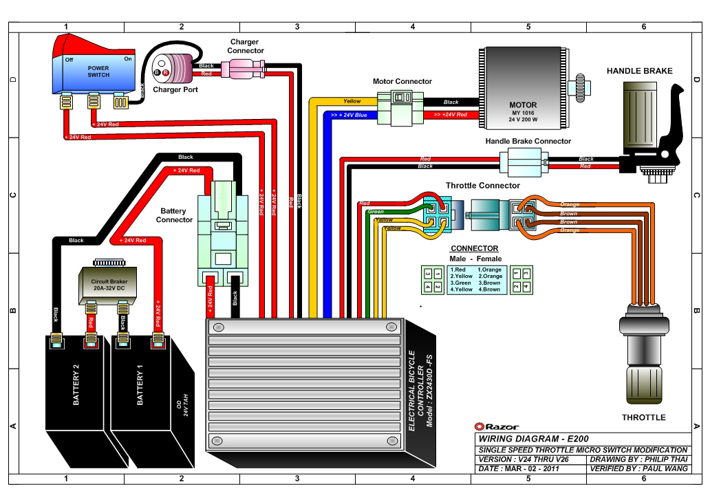
Razor Manuals
Electrical Scheme Of Wemos Lolin 32 Download Scientific Diagram

Led Lighting Circuit Diagram Tronicspro
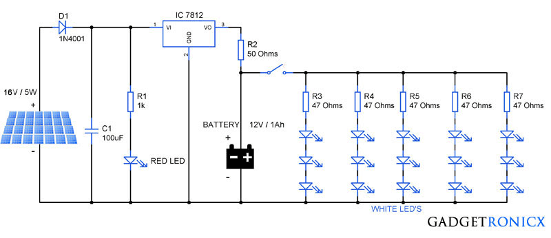
230v Ac Mains Operated Led Light Circuit Diagram Gadgetronicx
Relay Fuse Switch Kit Wiring Question Chevy Colorado Gmc Canyon

Index 32 Led And Light Circuit Circuit Diagram Seekic Com

Op Amp Led Flasher Oscillator Circuit Using Lm324
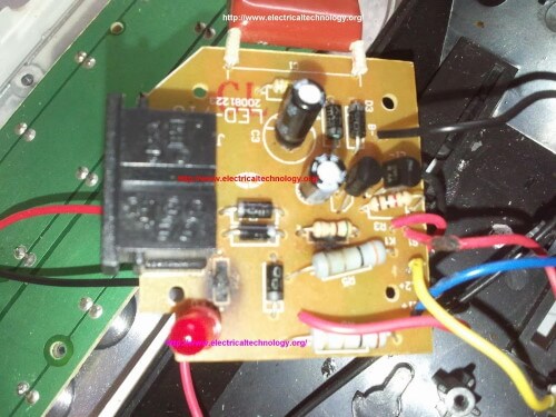
Emergency Led Light Circuit Dp 716 Rechargeable 30 Led S

Sme R D Company For Iot Wireless Products Led Glow Using Atmega32 Step By Step

Led Component Illustrated Diagram With Schematic Symbol Electronic Circuit Design Electronic Schematics Electronics Projects Diy

High Throughput Electrosynthesis Of Gradient Polypyrrole Film Using A Single Electrode Electrochemical System Analytical Chemistry

Index 32 Led And Light Circuit Circuit Diagram Seekic Com
Index 32 Led And Light Circuit Circuit Diagram Seekic Com

Amazon Com 32 Channel 96a Rgbw Dmx 512 Led Decoder Controller Dmx Dimmer Dc5 24v Rgbw Rgb Led Light 8 Bit 16 Bit Musical Instruments
What Is The Proper Wiring Configuration For 2 3 Way Duplex Switches Eaton 276w Box I M Trying To Wire A Fan And Light Separately But Can Only Find 3 Way Or Duplex Wiring Diagrams Do